

Consider a navigation data processor for a coastal patrol craft: an electronics box in a sealed below-deck bay, naval sheltered (NS) environment, three boards: a processor board, a power supply board, and an I/O board. The programme's allocation gives the box an MTBF budget of 40,000 hours. Every rate below is an illustrative teaching value chosen to walk the arithmetic; in a real study each λg and π comes out of the handbook tables for the exact part and conditions. One scope exclusion is declared up front: the boards' printed wiring assemblies and their solder connections are left out of the tables below to keep the arithmetic readable, and only the connectors are carried among the board-level terms. A released roll-up prices all three, and dropping any of them silently is one of the findings the pre-release check exists to catch.
The parts count pass
Board by board (rates in failures per 10⁶ h):
| Board | Part class | N | λg | π_Q | N·λg·π_Q |
|---|---|---|---|---|---|
| A · Processor | Microprocessor, 32-bit CMOS | 1 | 0.560 | 1.0 | 0.560 |
| A · Processor | SRAM, 4 Mbit | 2 | 0.410 | 1.0 | 0.820 |
| A · Processor | Flash, 64 Mbit | 1 | 0.480 | 1.0 | 0.480 |
| A · Processor | Crystal oscillator | 1 | 1.250 | 2.1 | 2.625 |
| A · Processor | Ceramic capacitors | 46 | 0.0041 | 3.0 | 0.566 |
| A · Processor | Film resistors | 38 | 0.0014 | 3.0 | 0.160 |
| B · Power | DC-DC converter hybrid | 1 | 3.200 | 1.0 | 3.200 |
| B · Power | Power MOSFETs | 4 | 0.180 | 2.4 | 1.728 |
| B · Power | Schottky diodes | 6 | 0.120 | 2.4 | 1.728 |
| B · Power | Tantalum capacitors | 12 | 0.0630 | 3.0 | 2.268 |
| B · Power | Power inductors | 4 | 0.0300 | 3.0 | 0.360 |
| C · I/O | RS-422 transceivers | 6 | 0.240 | 1.0 | 1.440 |
| C · I/O | Optocouplers | 8 | 0.310 | 1.0 | 2.480 |
| C · I/O | Circular connectors, 55-pin | 2 | 0.520 | 1.0 | 1.040 |
| C · I/O | Board-edge connectors | 3 | 0.310 | 1.0 | 0.930 |
| C · I/O | LED indicators | 5 | 0.0350 | 1.0 | 0.175 |
Summing per board and up to the system:
| Level | λ (f/10⁶ h) | Share |
|---|---|---|
| Board A: Processor | 5.211 | 25.3% |
| Board B: Power | 9.284 | 45.2% |
| Board C: I/O | 6.065 | 29.5% |
| System | 20.560 | MTBF ≈ 48,600 h |
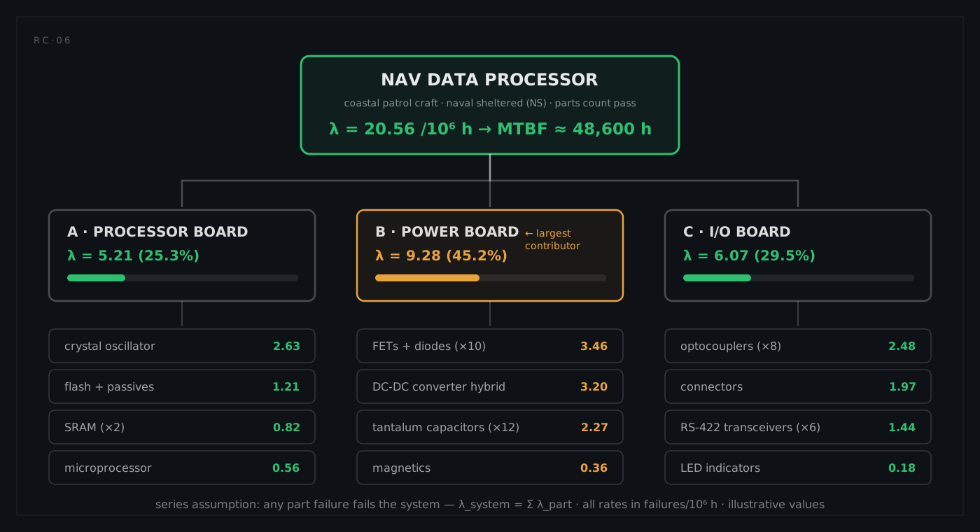
The headline: λ = 20.56 f/10⁶ h, MTBF ≈ 48,600 h. The box meets its 40,000-hour allocation with about 21% margin. But the roll-up's real product is the Pareto underneath it. The power board carries 45% of the system's failure rate; within it, the switching devices and the DC-DC hybrid dominate, and the twelve tantalum capacitors at 2.268 contribute more than the processor board's four microcircuits at 1.860 put together. The worst single part in the box is the DC-DC converter hybrid at 3.200, and the worst part on the processor board is the crystal oscillator at 2.625, whose commercial-grade quality factor of 2.1 more than doubled a 1.250 base rate: one line item, and the cheapest fix on the page. Three actionable findings from one afternoon of arithmetic, before any hardware exists.
Refining one part with the part-stress model
Now the thermal analysis arrives and reports the microprocessor's worst-case junction temperature: TJ = 88 °C. The microcircuit part-stress model is λp = (C₁·πT + C₂·πE)·πQ·πL. Walking it through with illustrative coefficients, C₁ = 0.28 (die complexity), C₂ = 0.055 (package), πE = 4.0 (NS, microcircuits), πQ = 1.0 (Class B), πL = 1.0 (mature production):
First the temperature factor, using the microcircuit form with its 0.1 coefficient and a 0.35 eV activation energy (digital MOS class):
1/TJ − 1/298 = 1/361 − 1/298 = −5.856×10⁻⁴
−(Ea/k) · (1/TJ − 1/298) = −(0.35 / 8.617×10⁻⁵) × (−5.856×10⁻⁴) = 2.379
πT = 0.1 × e^2.379 = 1.08
Then the model:
λp = (0.28 × 1.08 + 0.055 × 4.0) × 1.0 × 1.0 = 0.302 + 0.220 = 0.52 f/10⁶ h
Two things worth noticing. The part-stress result (0.52) sits close to the parts-count default (0.56); this box's thermal design is about as good as the handbook's average assumption. And the package term (0.22) is a fixed cost the environment sets: even a perfectly cooled die keeps it.
The model earns its keep in sensitivity. Suppose a packaging change blocks the airflow and TJ climbs to 110 °C: the same arithmetic gives πT = 2.06 and λp = 0.80, a 53% increase in the part's failure rate from 22 degrees of temperature. That is the Arrhenius lever in action, and it is exactly the kind of quantified argument that wins a thermal-design debate.
The calendar view: adding duty cycle and dormancy
The 48,600-hour MTBF above runs on the operating-hour clock. Now put the box on a real boat. The craft is underway (processor energised) about 30% of the calendar; the rest is harbour time with the system shut down in its bay. Take an illustrative dormant rate of 0.90 f/10⁶ h for the de-energised box (a few percent of the active rate, in line with dormancy conversion practice for electronics in benign stowage):
λcalendar = 0.30 × 20.56 + 0.70 × 0.90 = 6.168 + 0.630 = 6.80 f/10⁶ calendar hours
MTBFcalendar = 10⁶ / 6.80 ≈ 147,000 calendar hours
Same box, same design, two true MTBFs (48,600 hours against the operating clock, roughly 147,000 against the calendar) and a factor of three between them that is pure bookkeeping, not reliability. When the operator's field data eventually arrives measured in calendar time, this is the conversion that decides whether the fleet is "meeting prediction" or "missing it by 3×".
The same machinery answers mission questions directly, provided the right clock is used. A 14-day patrol is 336 hours with the box energised throughout, so the patrol runs on the operating rate, not the calendar one:
R = e^(−20.56×10⁻⁶ × 336) = e^(−0.00691) ≈ 0.9931
That is a 0.69% chance the patrol sees a processor failure. Eight such patrols a year are what a 30% duty cycle amounts to, and the annual expectation (~5.4%) is the number the support conversation should actually be about.