

Derating rests on two facts about parts and one about arithmetic. Parts fail more often the harder they are driven; they fail more often the hotter they are; and a prediction already contains both effects as multiplicative factors, so the design decision and the reliability number are the same decision written twice.
The two axes
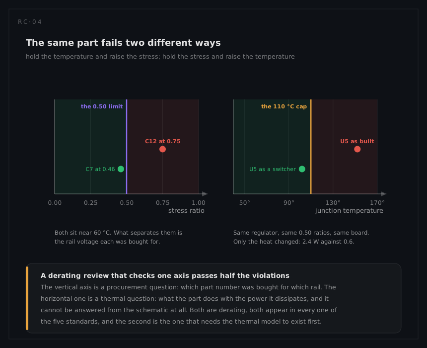
The stress ratio is S = applied / rated, computed per stress type and per part family. A part has several: a MOSFET has a drain-source voltage ratio, a current ratio and a power ratio, and it is derated on all of them at once, against whichever ceiling its family's rule carries. The ratio is a property of the circuit and the part number, and it can be read off a schematic and a parts list.
Temperature is not a ratio. It is the temperature the part itself reaches, which for a semiconductor is its junction:
TJ = Tambient + θJA · P, or TJ = TC + θJC · P where the case temperature is known
and the rule sets cap it directly, typically well below the part's own maximum. This is the axis that needs the thermal analysis to exist, and the axis on which a part that passes every ratio still fails.
| Axis | Answer comes from | Fixed by |
|---|---|---|
| Stress ratio | The schematic and the parts list | A different part number, or a different operating point |
| Temperature | The thermal model, at the worst-case environment | Less dissipation, better conduction, or a cooler place on the board |
The anatomy of the curve
A rating curve has three parts, and every derating curve inherits them:
| Feature | What it is |
|---|---|
| The flat region | Up to the reference temperature, the full rating applies |
| The knee | The reference temperature, where the part starts losing capability |
| The ramp | A linear fall to zero at the part's maximum temperature |
For a resistor rated P₀ at Tknee and zero at Tmax, the manufacturer's curve is
Prated(T) = P₀ for T ≤ Tknee, and P₀ · (Tmax − T)/(Tmax − Tknee) above it
and the programme's allowed power is that multiplied by the policy factor, with the whole curve truncated at the policy's own temperature cap. The worked example's resistor is a quarter watt at 70 °C, and a 50 per cent policy allows it 125 mW to the knee, 103 mW at 85 °C and 44 mW at 125 °C.
Which stresses, per family
Every rule set enumerates the same kind of table: the part family down the side, the stress types across, the ceiling in the cells, and a temperature cap per family. The families are conventional, and so are the stresses that matter:
| Family | Stresses that carry the rule |
|---|---|
| Resistors | Power, and for high values the voltage across the element |
| Ceramic capacitors | Voltage, and temperature against the dielectric's own limit |
| Solid tantalum capacitors | Voltage, severely, plus a circuit-impedance condition |
| Diodes and rectifiers | Reverse voltage, forward and surge current, junction temperature |
| Transistors and MOSFETs | Voltage, current, power, junction temperature, safe operating area |
| Integrated circuits | Supply voltage, output current, fan-out, junction temperature, frequency |
| Relays and switches | Contact current by load type, coil voltage, cycles |
| Magnetics | Current, hot-spot temperature, voltage per turn |
| Connectors | Contact current, voltage between adjacent contacts, insertion cycles |
Two subtleties in that table are where reviews go wrong. Solid tantalum capacitors are the classic: their voltage derating is the most severe in most rule sets, and several add a series impedance requirement that has nothing to do with a ratio at all. And relay and switch ratings are quoted by load type, so a contact rated 5 A resistive is not rated 5 A into a motor or a lamp.
The impedance condition is worth making concrete, because it is the half of the tantalum rule that a ratio-only review cannot see. MIL-HDBK-217F prices it as a series resistance factor applied to solid tantalum styles and to nothing else. Its argument is the effective resistance between the capacitor and its supply, divided by the voltage applied to the capacitor:
| Circuit resistance, ohms per volt | πSR |
|---|---|
| Above 0.8 | 0.66 |
| Above 0.6, up to 0.8 | 1.0 |
| Above 0.4, up to 0.6 | 1.3 |
| Above 0.2, up to 0.4 | 2.0 |
| Above 0.1, up to 0.2 | 2.7 |
| 0.1 and below | 3.3 |
A tantalum decoupling a stiff, low-impedance rail therefore carries five times the failure rate of the same part behind an ohm per volt, at exactly the same voltage ratio. A rule set that states a minimum circuit impedance for tantalum is asking for the same thing in the same units, and the check needs a number the schematic does not usually carry: the source resistance the part actually sees.
Application classes
Rule sets grade the application, and the ceilings move with the grade. NASA EEE-INST-002 organises its instructions around part quality Levels 1, 2 and 3; other documents distinguish by mission criticality or by whether the equipment is manned, long-life or expendable. The engineering content of the grade is simple: a part that cannot be replaced, on a mission that cannot be repeated, is derated harder.
The class is a programme decision recorded once, and it belongs beside the rule set's name in the derating policy. Two boards analysed at two different classes cannot be compared, and a report that does not state the class has not stated its result.
What derating buys, in the prediction's own terms
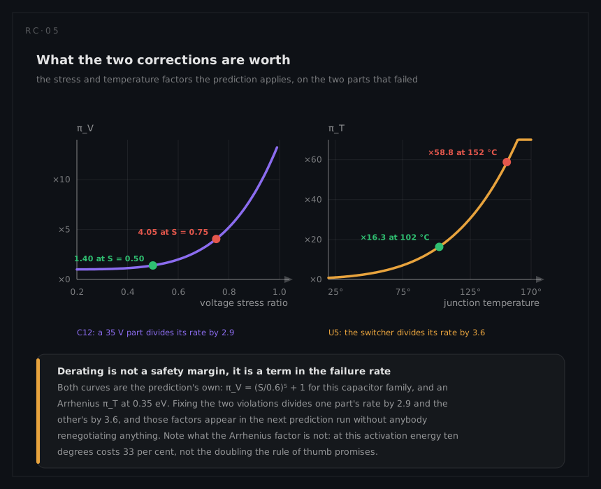
A stress ratio enters the prediction as a stress factor. MIL-HDBK-217F offers five voltage-stress columns for capacitors and puts solid tantalum on the steepest of them:
πV = (S / 0.6)¹⁷ + 1
which is indistinguishable from 1 below half rated voltage and violent above it: at S = 0.5 it is 1.05, at S = 0.75 it is 45.4, and at rated voltage it is close to 6,000. That exponent is the arithmetic underneath the rule that tantalum is derated hardest. The shallowest of the five columns is a cube, and it prices the same two ratios at 1.58 and 2.95: on that family, running at 0.75 instead of 0.50 costs a factor of under two, and on solid tantalum it costs a factor of 43. Temperature enters as an Arrhenius factor:
πT = exp[ −(Ea / k) · (1/T − 1/Tref) ]
with T in kelvin. At Ea = 0.35 eV a junction at 110 °C carries 20.5 times its 25 °C rate and one at 152 °C carries 58.5.
That last pair is worth holding onto, because it corrects a rule of thumb. "The rate doubles every ten degrees" is a statement about an activation energy near 0.7 eV. At 0.35 eV the same ten degrees costs about a third more at 100 °C, and less than that as the part gets hotter. Both numbers are common in real parts, so the honest version of the rule is that ten degrees is worth somewhere between a third and a doubling, and which one depends on the dominant mechanism.
What derating is not
- It is not a substitute for margin analysis. Derating checks steady-state stresses against ratings. Inrush, fault currents and supply transients belong to the worst-case circuit analysis, switching excursions to the safe-operating-area check, and single-event effects to the radiation analysis: separate work with its own limits, and named in the derating report so the gap is visible.
- It is not a wear-out model. A part inside its derating limits can still wear out: electrolytic capacitors dry, connectors fret, solder joints cycle. Derating slows those mechanisms; it does not remove them.
- It is not free. Derating a part means buying a larger, heavier, costlier one, or spending board area on heat. The trade is real and the prediction is what prices it.
- It says nothing about whether the circuit works. A part can be beautifully derated and functionally wrong.