

Consider the power-distribution board of a small satellite: the card that takes the regulated bus, protects it, and feeds the payload and the avionics. It is deliberately none of the systems the industry examples carry. The ratings and the limits below are illustrative teaching values in the shape the standards use, and a real analysis takes them from whichever of the five documents the contract names.
The policy, settled once:
| Policy item | This analysis |
|---|---|
| Rule set | One named standard, applied to every part on the board |
| Application class | Long-life, unmanned, not repairable |
| Stress-ratio ceilings | 0.50 for tantalum, relays and resistor power; 0.75 for semiconductors and magnetics |
| Temperature caps | 110 °C junction for semiconductors, 85 °C for tantalum and relays, 125 °C for the resistor, 130 °C hot spot for magnetics |
| Operating condition | Hot case: 55 °C baseplate, maximum bus voltage, full payload load |
The board, on both axes
Eight parts, each with its applied stress, its own temperature from the thermal model, and the two checks:
| Part | Applied | Rated | S | Allowed | Temp | Cap | Verdict |
|---|---|---|---|---|---|---|---|
| R14 · metal-film resistor | 0.09 W | 0.25 W at 70 °C | 0.44 | 0.50 | 85 °C | 125 °C | pass |
| C7 · solid tantalum | 16 V | 35 V | 0.46 | 0.50 | 60 °C | 85 °C | pass |
| C12 · solid tantalum | 12 V | 16 V | 0.75 | 0.50 | 62 °C | 85 °C | over on ratio |
| Q3 · power MOSFET | 48 V | 100 V | 0.48 | 0.75 | 73 °C | 110 °C | pass |
| D2 · rectifier diode | 1.9 A | 3.0 A | 0.63 | 0.75 | 88 °C | 110 °C | pass |
| U5 · linear regulator | 2.4 W | ratios all ≤ 0.50 | 0.50 | 0.75 | 152 °C | 110 °C | over on temperature |
| K1 · relay contacts | 3.2 A | 5 A resistive | 0.64 | 0.50 | 70 °C | 85 °C | over on ratio |
| L2 · inductor | 2.1 A | 3.0 A | 0.70 | 0.75 | 95 °C | 130 °C | pass |
Three violations in eight parts, and they are not the same kind of finding.
C12 and K1: over on the stress ratio
The capacitor is the classic. Somebody needed a 12 V rail decoupled, found a 16 V tantalum in the library, and used it: 12 / 16 = 0.75 against a ceiling of 0.50. Nothing about the board is hot, nothing is unusual, and the part is inside its own rating. It is a procurement decision that was never checked, and it is fixed by a part number: a 35 V part on the same rail gives 12 / 35 = 0.34.
The relay is the same shape with a twist. Its contacts are rated 5 A resistive, and the 3.2 A they carry is into a capacitive payload load, which is the condition its rating was not quoted at. Even on the resistive number it is 0.64 against 0.50.
Both tantalums also carry something no ratio column shows, and its status is worth stating exactly: the policy above sets ceilings and caps and no minimum circuit impedance, so neither part is in violation of it and the verdict column is right. What the impedance does is not judge the parts but price them. C7 and C12 sit directly across low-impedance rails, and at a source resistance of a tenth of an ohm C12's circuit resistance is 0.1 / 12 ≈ 0.008 ohms per volt, the bottom band of the series-resistance table in the foundations chapter, so both parts take πSR = 3.3 in the prediction. That factor multiplies whatever the voltage ratio has already done, and no larger capacitor removes it: it is fixed by putting resistance in front of the part, by choosing a family that does not care, or by buying the margin back on the voltage axis, where the exponent is steep enough to pay for it several times over. Two things follow. A review that reads only the ratio column records C7 as a clean pass and never meets the factor at all, and a rule set that does state a minimum impedance, as several of them do, would turn the same arithmetic into a violation on both tantalums, C7 included.
U5: over on temperature, with every ratio comfortable
The regulator's input voltage is half its rating, its output current is half its rating, and every stress ratio on the row passes with room to spare. It is a linear regulator dropping 2.4 watts in a package with a 28 K/W junction-to-ambient resistance, in a local ambient of 85 °C:
TJ = 85 + 28 × 2.4 ≈ 152 °C
against a 110 °C cap: 42 degrees over, on a part that a ratio-only review passes without comment. This is the case the foundations chapter means by the second axis, and it cannot be found on a schematic.
What the two fixes are worth
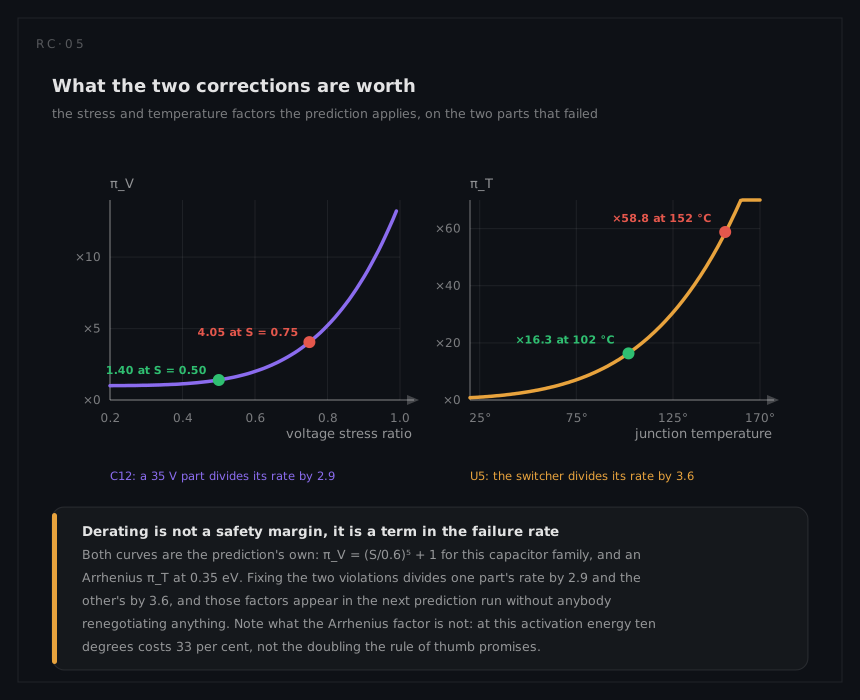
Derating is not a margin for its own sake, and the prediction says what each fix returns.
C12, through the voltage stress factor πV = (S/0.6)¹⁷ + 1, the column MIL-HDBK-217F gives solid tantalum:
at S = 0.75: (0.75/0.6)¹⁷ + 1 = 45.4 · at S = 0.50: (0.50/0.6)¹⁷ + 1 = 1.05 · at S = 0.34: (0.34/0.6)¹⁷ + 1 = 1.00
Changing one part number divides that capacitor's failure rate by 45, and the part costs the same. Read the three values together, because they carry a second lesson: 43 of that 45 is bought simply by getting under the 0.50 ceiling, and the extra margin from 0.50 down to 0.34 adds almost nothing. On a factor this steep the ceiling is where the whole benefit sits, which is the case for writing a policy as a ceiling and not as a target to beat.
U5, through the Arrhenius factor at Ea = 0.35 eV:
| Junction temperature | πT |
|---|---|
| 25 °C reference | 1.0 |
| 102 °C, as a switching regulator | 16.4 |
| 110 °C, the cap | 20.5 |
| 152 °C, as built | 58.5 |
Replacing the linear regulator with a switcher takes the dissipation from 2.4 W to about 0.6 W, which puts the junction at 85 + 28 × 0.6 ≈ 102 °C: inside the cap, and 3.6 times less failure rate than as built. The switcher costs board area and some EMC work, and that is the trade the number is there to inform.
The margin on everything else
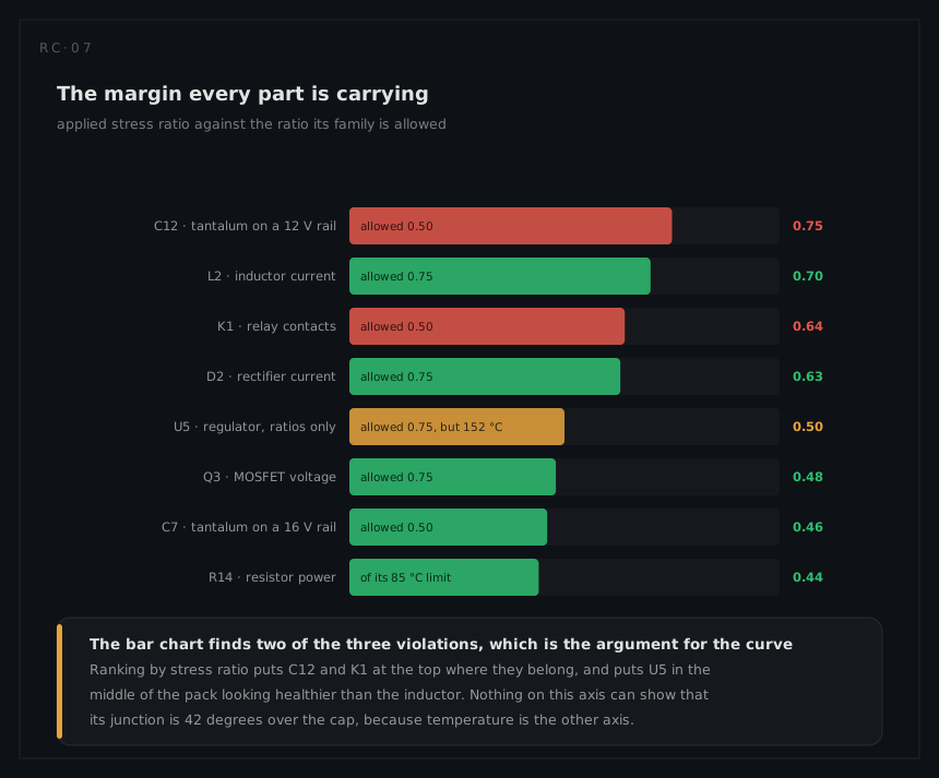
The passing parts are worth reading too. L2 sits at 0.70 against 0.75 and D2 at 0.63 against 0.75: 0.05 and 0.12 of ratio left, on parts whose loads are the ones most likely to grow. A load increase, a hotter orbit or an end-of-life tolerance moves either of them over. A derating report that lists only the violations has thrown away the early warning, which is the whole reason to keep the margins in the deliverable.
The same two parts show what the application class is worth. Nothing about the board changes if the contract calls up a stricter class whose semiconductor and magnetics ceiling is 0.60 rather than 0.75, but the verdicts do: D2 at 0.63 and L2 at 0.70 both become violations, and a board with three findings becomes a board with five. That is why the class belongs in the policy beside the rule set, and why two boards graded differently cannot be compared on their violation counts.
What the board looks like after the fixes
| Change | Effect |
|---|---|
| C12 → 35 V part | S from 0.75 to 0.34; that capacitor's rate ÷ 45 |
| K1 → 10 A contacts, or a solid-state switch | S from 0.64 to 0.32, and the load-type mismatch removed |
| U5 → switching regulator | TJ from 152 °C to 102 °C; that regulator's rate ÷ 3.6 |
| L2, D2 flagged | Inside policy with 0.05 and 0.12 of ratio left, watch on any load change |
Three part changes, no redesign, and they were available at schematic stage for the cost of noticing. That is the argument for running derating early: the same three findings after qualification are three requalifications.